Orbit: Difference between revisions
From Rise: The Vieneo Province
(Document fastest powered rendezvous, early ascent transfer, and MEET/fuel comparison) |
(Clarify RENDEZVOUS reselection and continuous-arc cutoff display) |
||
| Line 95: | Line 95: | ||
| LEFT / ALL USED || During orbital DOR execution: the active guidance correction remaining, in m/s, and all fuel consumed since engagement, in kg. ALL USED includes the armed wait and ascent when starting from the ground, as well as alignment, both burns, coast and corrections; it is not a B1-only or B2-only measurement. | | LEFT / ALL USED || During orbital DOR execution: the active guidance correction remaining, in m/s, and all fuel consumed since engagement, in kg. ALL USED includes the armed wait and ascent when starting from the ground, as well as alignment, both burns, coast and corrections; it is not a B1-only or B2-only measurement. | ||
|- | |- | ||
| MECO ~mm:ss || Estimated time to cutoff of the current orbital burn, shown beside BURN or ARRIVAL. It follows measured convergence and throttle-down, not the original B1/B2 duration. It may increase after a correction. --- means no reliable recent convergence estimate. ALIGN, WAIT, COAST, continuous ascent and reentry do not show this timer. | | MECO ~mm:ss || Estimated time to cutoff of the current orbital burn, shown beside BURN or ARRIVAL. It follows measured convergence and throttle-down, not the original B1/B2 duration. It may increase after a correction. --- means no reliable recent convergence estimate. ALIGN, WAIT, COAST, continuous ascent and reentry do not show this timer. A powered station transfer with separate burns uses its scheduled finite-burn cutoff instead of the ordinary convergence estimate; a continuously supported main arc has no discrete MECO timer. Cutoff is controlled by guidance, not by the countdown; another correction may subsequently fire. | ||
|} | |} | ||
| Line 182: | Line 182: | ||
# When cleared to turn toward the orbital direction, change '''STEER''' to '''ORBIT'''. This is allowed during execution. No automatic turn is authorized merely by passing 17 km. AFCS may be selected again if needed; monitor the changed flight path. | # When cleared to turn toward the orbital direction, change '''STEER''' to '''ORBIT'''. This is allowed during execution. No automatic turn is authorized merely by passing 17 km. AFCS may be selected again if needed; monitor the changed flight path. | ||
# Monitor IAS/Vne, AFT, pitch, thrust, fuel and AP/PE. The controller uses current mass, measured aerodynamic forces and separate thrust limits. Pitch and wing lift are preferred for a supported climb, with vertical RCS retained for VTOL, insufficient lift and recovery. Small vertical-thruster corrections are reduced while lift is available and climb rate is tracking. Attitude RCS assistance fades as the available wing/control-surface lift reserve grows, and remains available for VTOL or insufficient aerodynamic authority. Atmospheric heading changes use banked AFCS HDG turns, not orbital flat yaw. DOR keeps HDG/PIT through at least 50 km MSL and until modeled dynamic pressure is at most 500 Pa; a descent to 45 km or pressure rising to 750 Pa restores aircraft steering. These are DOR transition settings, not an atmospheric boundary. If wing reserve runs low before the transition, pitch uses RCS assistance. Above 50 km, a bank limit below one degree shows '''HDG LIMITED / RCS PIT''' on DOR: pitch assistance remains, but significant banked heading changes are unavailable in that interval. The FMA retains HDG/PIT until the orbital handoff. Main thrust can use full available authority when required, but follows the requested airspeed and climb rate, so a partial setting can be normal. Near insertion, small corrections use '''INSERTION / LEVEL TRIM''': level pitch with small main/reverse and translation-RCS corrections. Larger corrections can still require a pitched thrust vector. The initial speed schedule leaves margin below Vne. A short-term forecast at 95% Vne or 100°C AFT removes positive main thrust and shows '''ASCENT LIMIT / IDLE'''; this is a controller margin, not a guarantee against disturbances. | # Monitor IAS/Vne, AFT, pitch, thrust, fuel and AP/PE. The controller uses current mass, measured aerodynamic forces and separate thrust limits. Pitch and wing lift are preferred for a supported climb, with vertical RCS retained for VTOL, insufficient lift and recovery. Small vertical-thruster corrections are reduced while lift is available and climb rate is tracking. Attitude RCS assistance fades as the available wing/control-surface lift reserve grows, and remains available for VTOL or insufficient aerodynamic authority. Atmospheric heading changes use banked AFCS HDG turns, not orbital flat yaw. DOR keeps HDG/PIT through at least 50 km MSL and until modeled dynamic pressure is at most 500 Pa; a descent to 45 km or pressure rising to 750 Pa restores aircraft steering. These are DOR transition settings, not an atmospheric boundary. If wing reserve runs low before the transition, pitch uses RCS assistance. Above 50 km, a bank limit below one degree shows '''HDG LIMITED / RCS PIT''' on DOR: pitch assistance remains, but significant banked heading changes are unavailable in that interval. The FMA retains HDG/PIT until the orbital handoff. Main thrust can use full available authority when required, but follows the requested airspeed and climb rate, so a partial setting can be normal. Near insertion, small corrections use '''INSERTION / LEVEL TRIM''': level pitch with small main/reverse and translation-RCS corrections. Larger corrections can still require a pitched thrust vector. The initial speed schedule leaves margin below Vne. A short-term forecast at 95% Vne or 100°C AFT removes positive main thrust and shows '''ASCENT LIMIT / IDLE'''; this is a controller margin, not a guarantee against disturbances. | ||
# In standalone PARKING ORBIT, after parking-orbit insertion settles, DOR disconnects with the usual sound and shows '''INSERTION COMPLETE / REPLAN'''. Select RENDEZVOUS and inspect a new plan from the achieved orbit to reach the station. | # In standalone PARKING ORBIT, after parking-orbit insertion settles, DOR disconnects with the usual sound and shows '''INSERTION COMPLETE / REPLAN'''. Select RENDEZVOUS and inspect a new plan from the achieved orbit to reach the station. Selecting RENDEZVOUS starts a new FASTEST search. To keep a particular appointment instead, edit MEET and review the resulting plan before engagement. Standalone PARKING ORBIT does not automatically complete rendezvous or switch to TVM; ground RENDEZVOUS continues automatically as described above. | ||
'''Ascent forecast indications:''' '''IAS EST''' and '''AFT EST''' are short-term predictions, not the measured PFD IAS or current airframe temperature. Each forecast turns red only when it exceeds its own displayed limit. '''ASCENT LIMIT / IDLE''' leaves DOR engaged while removing positive main thrust; climb thrust can resume when the forecast clears. Continue monitoring actual IAS, AFT and the flight path. | '''Ascent forecast indications:''' '''IAS EST''' and '''AFT EST''' are short-term predictions, not the measured PFD IAS or current airframe temperature. Each forecast turns red only when it exceeds its own displayed limit. '''ASCENT LIMIT / IDLE''' leaves DOR engaged while removing positive main thrust; climb thrust can resume when the forecast clears. Continue monitoring actual IAS, AFT and the flight path. | ||
Revision as of 05:58, 30 October 2026
The Digital Orbital Resolver (DOR) is the spacecraft's orbital guidance and control system. Its Orbit MFD shows your current trajectory, the selected target's trajectory, and a proposed maneuver around Vieneo. Use it to change your orbit, rendezvous with a station or another spacecraft, or pass over a selected surface point. DOR executes the selected valid orbital plan; circularizing is one possible plan.
The full-page instrument is installed in the E-10, E-11, P-13, W-6, and EVA displays.
Illustrations: Instrument examples show selected maneuvers and readouts. Example times, fuel and delta-V depend on the illustrated conditions and do not predict your vehicle's performance. Some panels use alternate labels such as MIN ROUTE ALT and TO GO / USED; use the readout descriptions below to interpret them.
Ground rendezvous: Select MODE RENDEZVOUS on the ground to plan and fly VTOL launch, ascent and transfer to an orbital station or spacecraft as one DOR mission. For a supported station, DOR can begin a powered intercept before parking-orbit capture finishes. See Ground-to-rendezvous mission. Standalone MODE PARKING ORBIT ends at the parking orbit. Ground-to-ground SURFACE PLAN remains planning-only.
Operating scope: Orbital adjustment, rendezvous and overflight have executable plans. SURFACE PLAN remains planning-only for ground and low-atmospheric departures. The automated-entry controller adds REENTRY execution from orbit to an atmospheric handoff, followed by aircraft guidance and TAS hold. FINAL HOLD captures altitude; runway ILS/VISUAL handoffs retain a descent. With FINAL ILS selected before entry, the aircraft controller continues a steep descent into a descending 3-degree localizer/glideslope intercept. VISUAL continues to the same final geometry, with final approach left to the pilot. Flare and touchdown remain manual. Entry execution requires an ENTRY READY indication; PLAN ONLY is a preview, not a flight command.
Open and operate the page
The page is identified as DOR at the upper left. On the ground, the launch header shows SEARCH while comparing candidates and ARMED while DOR is awaiting comparison or departure. NO FIT or FUEL identifies an unavailable or fuel-short launch estimate. While executing, EXEC at the upper right and the active phase (ALIGN, WAIT, BURN, COAST or ARRIVAL) blink together: one second visible, one second hidden. Normal active phases are green; a separate red warning does not turn BURN or ARRIVAL red. The phase and its MECO estimate blink together. The DOR page identifier, other numerical readouts and atmospheric warnings stay steady. ESTIMATE, NO PLAN and completion/fault indications do not use this execution blink.
Static illustrations do not show the flashing execution indications.
Select the Orbit page on a supported vehicle's MFD. Choose the station, spacecraft or surface waypoint on your usual target-selection instrument; Orbit reads that selection. You do not enter a second waypoint on this page.
| Control | Action |
|---|---|
| Shift + Up / Down | Select a row in the side controls. The highlighted row's actions appear along the bottom. |
| Shift + Left / Right | Change the highlighted option or decrease/increase its value. |
| Shift + C, with the eccentricity row selected | Request a circular orbit (e = 0). |
| Your configured DOR on/off control | Engage or disengage a valid executable plan. SURFACE PLAN stays planning-only. The automated-entry controller can execute an ENTRY READY reentry; after handoff, the same control cancels its TAS hold. |
The controls require cockpit power and do not take these keys while text entry is active. Changing VIEW does not alter the plan or interrupt DOR. Changing a planning value does interrupt execution: review the new solution before engaging DOR again. Standalone PARKING ORBIT offers STEER AFCS / ORBIT as a live heading-source choice during the climb. Ground RENDEZVOUS selects its staging orbit and orbital steering automatically.
Planning wait: COMPUTING PLAN or REFRESHING PLAN means a current solution is still being calculated. Engaging DOR while that calculation is pending shows DOR ARMED / PLANNING and commands no thrust or attitude change until a current, valid plan is available. In flight, this waiting state does not hold altitude or speed; continue monitoring the trajectory and take control if necessary. A changed target, mission setting or materially changed flight state requires a fresh solution. Changing VIEW does not cancel the calculation. PLANNER UNAVAILABLE means no result was accepted; review the state before trying again. A completed calculation must still satisfy the usual engagement checks.
Selecting Orbit does not replace or acknowledge EICAS indications. With EICAS powered and serviceable, its gear, engine, trim and crew-alert indications remain independent of the MFD page. If an indication disappears unexpectedly, do not assume the underlying condition has cleared.
Select an objective
| MODE | Use |
|---|---|
| RENDEZVOUS | An orbiting station or free-flying vessel is selected. Reach its trailing staging point and match its velocity. On the ground, this includes launch, ascent and an automatic transfer; a supported station intercept can begin before parking-orbit capture finishes. |
| OVERFLY | A surface waypoint or grounded vessel is selected. Pass above that rotating ground point at the requested altitude and time. |
| SURFACE PLAN | A surface target is selected for a ground or low-atmospheric departure. Compare atmospheric, suborbital and orbital journeys using TRIP duration before departure and a PASS countdown afterwards. Planning only. |
| REENTRY | The surface-arrival objective for an orbital/high-altitude departure, including while docked at a station. Compare direct powered entry with coast-then-entry, ending upstream of the waypoint at the selected HANDOFF altitude and TAS. The automated-entry controller can execute a qualifying ENTRY READY plan after undocking. |
| PARKING ORBIT | Before orbit is established, perform VTOL liftoff or take over an airborne climb to a selected circular parking orbit. Main-engine pitch guidance uses current mass and atmospheric conditions. This standalone mode ends at insertion; choose RENDEZVOUS before launch for the continuous trip to an orbital target. |
| ADJUST ORBIT | Change your own orbit independently of the selected target. Available through MODE once the current bound orbit has its periapsis above the surface, including when a target is selected. It is not offered on the ground. |
A newly selected surface target defaults to the surface-arrival objective. It is labeled SURFACE PLAN for a ground/low-atmospheric departure or REENTRY for an orbital/high-altitude departure. An entry keeps its identity through the atmospheric handoff rather than becoming a new ground-departure plan. Use MODE to choose OVERFLY for an orbital pass or ADJUST ORBIT to change your own orbit. An explicitly selected ADJUST ORBIT objective remains independent of the target.
With an orbital target selected on the ground, MODE offers RENDEZVOUS and PARKING ORBIT. Once established in a bound orbit with periapsis above the surface, it offers RENDEZVOUS and ADJUST ORBIT; PARKING ORBIT is no longer offered. Without a target, choose PARKING ORBIT before orbit is established, ADJUST ORBIT in orbit, or select a navigation target elsewhere. A docked or contained target is not treated as an independent free-flying spacecraft. An undocked spacecraft inside a station's control area remains a valid target. An atmospheric-flight target may still have a predicted trajectory, but it is marked with an atmospheric warning.
Rendezvous is more than matching orbital size and shape. Two spacecraft can have identical orbital parameters and remain far apart. Rendezvous also solves for position and velocity at the same future time, including the difference between their orbital planes.
Read the picture and numbers
The graphic area stays the same size in every mode. In the ascent altitude/distance view, green is measured flight history and amber is the powered forecast (see Ground and ascent). In orbital views, green is your current trajectory; cyan is the target; amber dashed lines show the proposed transfer. Dim amber shows the destination orbit, and gray dashed lines show a planned coast before departure. AP and PE mark apoapsis and periapsis. In orbital plans, numbered amber markers identify burns; T identifies the target's current position. Ground-departure surface previews instead number phase boundaries and mark the future arrival point B. REENTRY uses D for deorbit, E for the 100 km crossing and H for atmospheric handoff; the legend identifies them.
| VIEW | What it helps you see |
|---|---|
| ORBIT | Your orbital plane viewed face-on: shape, apsides and transfer path. |
| PLANE 3D | Plane orientation, with Vieneo's equator and north axis as references. The NODE line indicates the intersection of the current and target orbital planes. |
| EDGE-ON | Your orbital plane viewed from its edge. Useful for seeing how far the target or transfer leaves that plane; it compresses the shape of your own orbit into a line. |
| TRACK | Latitude/longitude ground tracks, including Vieneo's rotation. Useful for a surface overflight. This is a schematic grid, not terrain imagery. |
| Readout | Meaning |
|---|---|
| AP / PE | Highest / lowest altitude of the orbit above the spherical Vieneo reference surface, in km. A negative PE means the unpowered trajectory intersects that surface. |
| e | Eccentricity: 0 is circular; larger values produce a more elongated ellipse. |
| SIZE … km MSL | Orbit size expressed as altitude above mean sea level. For a circle, this is the orbit altitude; for an ellipse, it is (AP altitude + PE altitude) / 2, not the time-average altitude. The planner adds Vieneo's 2939.6 km reference radius internally. |
| i / PLANE DIF | Inclination to Vieneo's equator, or the angle between your plane and the target's plane, in degrees. |
| TP / nu | Orbital period in seconds / true anomaly in degrees, locating you around the current orbit relative to periapsis. |
| CURRENT > FINAL | Current AP/PE/e followed by the proposed final orbit after all burns. This is not the transfer minimum. CURRENT > REQUEST is an editable goal for which no valid plan exists yet. |
| PLAN MIN ALT | Lowest checked planned-route altitude in km MSL above the spherical reference surface. Includes any waiting coast, transfer and continuing final orbit; an OVERFLY circularization check also includes its arrival-response allowance. This is separate from final PE and from the actual unpowered coast. |
| B1 / B2 | Planned burn time and delta-V in m/s. The IDEAL line gives duration in seconds and fuel in kg for the main-engine maneuver; it does not include all attitude control, RCS trims or later corrections. |
| TOTAL / IDEAL FUEL | Total planned delta-V and ideal main-engine fuel. The calculation uses current vehicle mass and engine performance, with mass decreasing as fuel is consumed. Real execution can use more fuel for alignment, RCS, finite burns and corrections. |
| LEFT / ALL USED | During orbital DOR execution: the active guidance correction remaining, in m/s, and all fuel consumed since engagement, in kg. ALL USED includes the armed wait and ascent when starting from the ground, as well as alignment, both burns, coast and corrections; it is not a B1-only or B2-only measurement. |
| MECO ~mm:ss | Estimated time to cutoff of the current orbital burn, shown beside BURN or ARRIVAL. It follows measured convergence and throttle-down, not the original B1/B2 duration. It may increase after a correction. --- means no reliable recent convergence estimate. ALIGN, WAIT, COAST, continuous ascent and reentry do not show this timer. A powered station transfer with separate burns uses its scheduled finite-burn cutoff instead of the ordinary convergence estimate; a continuously supported main arc has no discrete MECO timer. Cutoff is controlled by guidance, not by the countdown; another correction may subsequently fire. |
Minimum route altitude
Read PLAN MIN ALT directly below the graphic before engaging DOR. The graphic retains its size, and the OWN / TARGET / PLAN legend sits alongside the readout. It appears in every orbital view, including ascent detail when an orbital route is available. It uses the planner's checked arc minima, not the lowest vertex of the drawn curve.
- Red means the planned minimum is below 100 km MSL.
- Amber means the minimum is at least 100 km but the planned route has an atmospheric warning or is blocked by the clearance check.
- Neutral gray is an unflagged estimate, not flight clearance. --- means no checked route minimum is available; it never substitutes the final PE or current-coast minimum.
CURRENT > FINAL distinguishes the destination AP/PE from this route minimum. A final PE of 118 km does not establish the approach's minimum altitude, and pressure warnings depend on air-relative speed as well as altitude. The pressure advisory threshold is 10 Pa; a 118 km orbit is not automatically atmospheric. Atmospheric and surface-planning policies remain those of the selected mode; this display change does not add a new restriction to RENDEZVOUS or ADJUST ORBIT. SURFACE PLAN keeps its separate phase legend and planning-only readouts.
During EXEC, PLAN MIN ALT describes the committed route: the instantaneous-burn estimate for an ordinary orbital transfer, or the sampled finite path for a powered prograde station transfer. COAST MIN describes the current unpowered trajectory if no more burns occur; CORRECTION MIN describes the live powered-correction forecast. These are km MSL and need not agree: a planned minimum of 118 km can coexist with a negative COAST MIN while later burns are still needed. A negative value means the mathematical coast intersects Vieneo. These warnings remain separate from the green execution phase and any retained red abort reason. A fresh preview after an abort shows the new plan; the old abort reason remains available independently.
Ordinary orbital-transfer limitation: PLAN MIN ALT describes the instantaneous-burn plan, not the live powered recovery. The powered prograde station option instead checks its finite trajectory. DOR checks a finite powered response separately, including alignment time rather than an unpowered coast for the entire correction. A negative current PE during a burn can therefore coexist with a viable recovery, while still warning what would happen if thrust stopped. A neutral planned minimum or final PE is not assurance that DOR can complete the whole maneuver. See Powered correction clearance.

Orbital direction cautions
A steady amber caution beside the graphic's view title identifies the direction of the proposed plan. It remains visible during EXEC, including the hidden half of the execution blink, and does not replace atmospheric, fuel or finite-burn cautions.
- ORBIT REVERSAL means a departure or arrival burn changes the orbital angular-momentum direction by more than 90 degrees. It compares the directions before and after the burn; it is not based on which way the nose or thrust vector points. An ordinary backward braking burn that preserves orbital direction does not trigger it.
- RETROGRADE ORBIT means the transfer or final orbit runs against Vieneo's modeled rotation. A ship that already travels retrograde can keep that direction without an ORBIT REVERSAL. Polar motion alone is not classified as retrograde.
- RETROGRADE / REVERSAL shows both conditions. An intermediate retrograde transfer still warns even if the final orbit returns to prograde. The committed plan retains its caution during execution.
The OVERFLY automatic initial PASS search excludes plans that reverse orbital direction. Manual previews remain available with the caution. Direction caution alone does not block DOR, but the independent OVERFLY atmospheric-clearance requirements still apply. Blocked atmospheric previews retain their direction caution. If reversal was unintended, change the arrival/departure time or the overflight exit behavior and inspect the resulting plan before engaging DOR. A large delta-V can suggest reversal, but the warning is calculated from the trajectories rather than a speed threshold.
See the blocked-overfly illustration under Overfly atmospheric clearance. A low-periapsis route that fails those checks cannot be executed.
Powered prograde station transfer
A new RENDEZVOUS mission defaults to FASTEST (AUTO) on the ground and in orbit. DOR searches for the earliest accepted arrival before comparing fuel at that arrival time. Use MEET to add time and compare the recomputed fuel estimate. The automatic search excludes orbital reversals; reverse-main braking can slow the ship without reversing its orbital direction.
For stations, DOR compares ordinary orbital transfers with finite powered paths. These include unequal boost/brake periods, a main-engine burn followed by a gravity-driven coast and a matching burn, and shaped arcs that use main thrust to support the curvature as well as accelerate or brake. A powered arc can therefore hold a pitched attitude and keep thrust on between its main acceleration and braking periods. It does not assume small downward RCS can bend an arbitrarily fast path. The search also considers prograde paths that complete additional revolutions.
The powered candidates cover up to two hours from orbital departure, including alignment time. They require valid current vehicle and atmospheric data and are available for stations, not freely maneuvering vessels. Longer selected meetings can still use the ordinary orbital planner within the six-hour horizon. FASTEST is the earliest accepted candidate in a bounded search, not proof of the fastest physically possible trajectory.
MAIN ...% RCS ...% peak gives predicted peak engine and translation-RCS use. Separate burns show their BURN duration and fuel. A continuously supported main-engine arc instead shows POWERED ARC, MATCH and THRUST MAY REMAIN ON; it has no discrete MECO countdown. TOTAL FUEL includes modeled main, translation-RCS and idle consumption across the whole path. Attitude-control RCS and later tracking corrections are not included. The curve and PLAN MIN ALT describe the sampled finite path. Full available thrust is used only where the chosen path, response and operating margins allow it; FASTEST is not a command to hold 100% throughout.
Planning uses Vieneo's existing atmosphere, heat model, gravity and rotation, separate main/reverse/RCS authority, engine response, changing mass, fuel and aerospace-class loads. The powered path stays at least 100 km MSL and keeps a 5% reserve below the 10 Pa orbital pressure threshold; planned translation RCS stays below 80% of authority. IAS and AFT retain their 95% Vne and 100°C limits. These are modeled margins, not protection against every disturbance or loss of thrust.
On FMA2, forward main demand shows BURN, reverse demand shows BRAKE, and a controlled translation-RCS segment with negligible fore/aft thrust shows RCS. ALIGN stays in the attitude cells while DOR holds the required attitude, including through a scheduled coast within a powered transfer. A stable roll reference follows the transfer plane so passing through a near-vertical attitude does not reverse the roll command. Read ALIGN to distinguish controlled attitude from free-look COAST. Stale measurements show TRANSFER DATA WAIT with commands inhibited; fresh data resumes guidance. Changes of target, plan, power or flight state can still cancel execution. Successful matching hands over to TVM at the usual five-kilometre trailing point.
Ground and ascent
For a ground RENDEZVOUS or standalone PARKING ORBIT, the default ORBIT view shows ASCENT / ALTITUDE VS DISTANCE. The vertical axis is altitude in km MSL; the bottom axis is accumulated horizontal ground distance in km since departure. This is distance along the flown ground track, not range to the destination or slant distance. Taxi distance is excluded; a vertical VTOL climb remains at zero ground distance.
- PLAN EST (amber), labeled ASCENT EST in RENDEZVOUS, is the estimated powered climb through parking insertion, using the ascent controller, current loaded mass, gear configuration, wind, atmosphere and engine limits. Computation runs in the background. COMPUTING PLAN... and PLAN UNAVAILABLE identify missing forecasts. It is an advisory estimate, with approximate aircraft response, fixed weather/configuration and no terrain or obstacle check.
- ACTUAL (green) is the measured flight history, with a diamond at the latest position. Samples are retained approximately every kilometre horizontally, or earlier after a kilometre of altitude change or five seconds, preserving slow and vertical flight. The display updates approximately once a second. Long histories are progressively coarsened while retaining the departure point.
- The departure plan stays fixed after liftoff so deviations remain visible. Changing the orbit/steering/target regenerates the remaining forecast from the current distance; FROM ... km identifies that starting point. The forecast may update on the pad as the launch recommendation or aircraft setup changes.
- Flight history is collected automatically, including during manual departure. If observation starts airborne, DIST FROM PICKUP (km) identifies its origin. Landing, a vehicle or simulator change, or a flight-state reset starts a new history.
The axes scale to fit both traces. The ascent profile remains available in the default ORBIT view through parking-orbit insertion, including above 100 km. Change VIEW to PLANE 3D, EDGE-ON or TRACK to inspect orbital geometry without cancelling the climb. For RENDEZVOUS this amber curve is the parking fallback, not the whole intercept profile. DOR can leave it early for a powered station intercept. At the transfer handoff, the display changes to the actual orbital transfer plan. The header says ASCENT / INSERTION during the initial leg.
With an orbital target selected on the surface, choose RENDEZVOUS for launch through arrival, or PARKING ORBIT to stop after insertion. ADJUST ORBIT replaces PARKING ORBIT once an orbit is established.
For a vacuum orbital objective such as ADJUST ORBIT, ASCENT PROFILE REQUIRED means that objective has no executable powered launch. Choose MODE RENDEZVOUS for a complete trip to an orbital target, or MODE PARKING ORBIT for a separate powered climb ending at a parking orbit. Any ordinary vacuum transfer estimate starts from your measured position and velocity; it does not include lift or drag in that predicted path.
Outside an executable powered-ascent leg, the local ASCENT DETAIL / COAST view still shows the measured-state unpowered coast below 100 km. It returns to the selected orbital view at 100 km. This does not certify insertion: a periapsis intersecting Vieneo still indicates a suborbital trajectory. A descending vehicle is not automatically shown as ascending.
For SURFACE PLAN, the default view shows a fitting estimated powered ascent as ASCENT / PLAN ONLY. A rejected candidate is labeled ASCENT / INVALID PREVIEW. Change VIEW to PLANE 3D, EDGE-ON or TRACK to inspect the entire journey before takeoff; changing VIEW does not change the selected trip timing. The local surface view rotates with the departure location, so a vertical climb is not mistaken for sideways travel caused by Vieneo's rotation.
There is no hard atmospheric boundary at 75 or 100 km. The planner's warning estimate uses Vieneo's density profile and air-relative speed. The 100 km ascent-view transition is a display rule. OVERFLY separately uses 100 km as a minimum clearance policy and also checks dynamic pressure; neither use defines a physical atmospheric boundary.
Ground-to-rendezvous mission
Use this procedure to fly from the surface to an orbital station such as TAC without selecting a new plan in orbit.
- Select TAC on the navigation/target instrument and choose MODE RENDEZVOUS on DOR. Initially MEET shows FASTEST (AUTO) while DOR finds its earliest accepted arrival estimate. You can then adjust the countdown for a later or earlier meeting. DOR derives its intermediate insertion altitude from the station's orbital altitude and selects the target's orbital direction automatically; there are no ORBIT or STEER setup rows in this mission. PARK FALLBACK ...km MSL reports the parking goal used if an earlier powered intercept is unavailable. The ascent graph shows that fallback climb. Low stations can require a small additional height allowance so the insertion capture band remains above DOR's orbital altitude and dynamic-pressure limits: YSP near 118 km currently gives a staging goal near 121 km in Vieneo's standard model. For a coasting vessel, DOR uses its semi-major-axis altitude; automatic ascent is capped at 1000 km, with the orbital transfer covering any remaining height difference. This is a target-based staging policy, not an optimization over every possible insertion altitude.
- Review FACE ... deg T for the intended launch direction. The target's current bearing and closing range are not the required insertion heading or launch time. If ATC requires a different departure route, leave DOR off and fly that route manually; engage the retained rendezvous mission when cleared to proceed toward the orbital direction. Standalone PARKING ORBIT retains the optional HDG/NAV steering selection.
- Compare the launch recommendation, BOOST IN for an early powered-transfer departure or INSERT IN for parking insertion, ASC / XFER / TOTAL fuel and MEET -5m / +5m alternatives. During FINDING FASTEST RENDEZVOUS or COMPARING LAUNCH TIMES..., numbers may describe a provisional candidate; CANDIDATE / NOT COMMITTED is not a launch countdown. MEET must leave time for both ascent and transfer. A station that is close and approaching can still have no fitting solution at the chosen MEET.
- Leave LAUNCH AUTO to wait for the recommended departure. When VTOL is ready and automatic departure is authorized, engage DOR. It can remain armed while the comparison finishes, showing ARMED / COMPARING LAUNCHES with zero thrust and no attitude command. When a completed, current, fuel-fitting solution is available, ARMED / LAUNCH WAIT and LIFTOFF IN show its committed countdown. At zero, DOR starts VTOL automatically. LAUNCH NOW evaluates immediate departure only; RENDEZVOUS still waits for that completed, fuel-fitting estimate before liftoff.
- Start approximately level on a clear VTOL area with sufficient loaded vertical-thrust authority. Stow flaps and spoilers, close bays and clear icing. DOR lifts to approximately 750 m AGL in the E-10/E-11 (100 m in other supported vehicles), builds airspeed, and controls pitch and thrust through ascent and insertion. Retract the landing gear yourself after liftoff. Monitor IAS/Vne, AFT, fuel and the flight path.
- Leave DOR engaged during ascent. AUTO POWERED INTERCEPT means it can switch to an accepted station transfer once altitude, dynamic pressure and attitude-control conditions permit, before settling a parking orbit. It checks the transfer from the actual measured state and remaining fuel while retaining the original absolute MEET. Ascent guidance and thrust continue while this optional early calculation is pending; a rejected early candidate leaves the climb running. If no early candidate fits, DOR proceeds to the parking fallback and solves the remaining transfer there. The display then changes to the orbital plan. No MODE change, manual replan or second engagement is needed.
- Continue monitoring through alignment, departure burn, coast and arrival correction. Successful rendezvous ends at the normal roughly 5 km trailing staging point and hands over to TVM with zero selected closing speed. Obtain clearance and perform close approach/docking separately.
The ground comparison is an estimate, not a guarantee of the flown path, fuel use or completion exactly at MEET. Final settling can take additional time. If the achieved insertion state cannot support the transfer, DOR disconnects with a reason such as NO TRANSFER AT INSERTION, TRANSFER FUEL SHORTFALL or MEET BURN TIME LIMIT. An expired MEET or invalid target also stops execution. Take control, review the condition and select a new plan when appropriate; DOR does not silently move MEET or declare rendezvous complete at the parking orbit.
Automated ascent
MODE PARKING ORBIT provides a standalone powered climb ending at a circular parking orbit, including VTOL liftoff. The same ascent controller flies the first leg of a ground RENDEZVOUS mission. During atmospheric climb, DOR supplies heading and pitch targets to the ordinary AFCS HDG/PIT controllers and controls thrust. The FMA shows HDG and PIT on those axes. FPA remains available for pilot-selected flight. Select RENDEZVOUS before launch when the whole trip to an orbital target should continue automatically.
- Select MODE PARKING ORBIT on DOR when you want to stop at a parking orbit. Set ORBIT 200 km MSL as an example parking altitude; the range is 150–1000 km in 50 km steps.
- Use STEER AFCS to follow the selected HDG or NAV heading for an assigned departure. This chooses the source of the commanded heading, not whether control surfaces or RCS are used. DOR controls attitude and thrust while following that heading. The magenta orbital heading bug and the airborne ORBIT HDG … deg T readout show the desired orbital direction separately. Set the assigned heading or navigation route before engaging.
- Start approximately level on a clear VTOL departure area, with sufficient vertical-thrust authority for the current loaded weight. Flaps and spoilers must be stowed; icing and open bays are unsupported. A runway takeoff remains manual; PARKING ORBIT can also take over an airborne climb.
- Leave LAUNCH AUTO selected to arm the recommended departure: engage DOR to await the comparison and its recommended departure. While comparing it shows ARMED / COMPARING LAUNCHES with no thrust or attitude command. After accepting a completed, current, fuel-fitting estimate it shows ARMED / LAUNCH WAIT and LIFTOFF IN until departure, then starts VTOL automatically. Choose LAUNCH NOW for immediate departure instead. VTOL first lifts approximately level to 750 m AGL in the E-10/E-11 (100 m in other supported vehicles), then transitions to a climb using lift and pitch to direct the main engines. Retract the gear yourself after liftoff. DOR does not operate it.
- When cleared to turn toward the orbital direction, change STEER to ORBIT. This is allowed during execution. No automatic turn is authorized merely by passing 17 km. AFCS may be selected again if needed; monitor the changed flight path.
- Monitor IAS/Vne, AFT, pitch, thrust, fuel and AP/PE. The controller uses current mass, measured aerodynamic forces and separate thrust limits. Pitch and wing lift are preferred for a supported climb, with vertical RCS retained for VTOL, insufficient lift and recovery. Small vertical-thruster corrections are reduced while lift is available and climb rate is tracking. Attitude RCS assistance fades as the available wing/control-surface lift reserve grows, and remains available for VTOL or insufficient aerodynamic authority. Atmospheric heading changes use banked AFCS HDG turns, not orbital flat yaw. DOR keeps HDG/PIT through at least 50 km MSL and until modeled dynamic pressure is at most 500 Pa; a descent to 45 km or pressure rising to 750 Pa restores aircraft steering. These are DOR transition settings, not an atmospheric boundary. If wing reserve runs low before the transition, pitch uses RCS assistance. Above 50 km, a bank limit below one degree shows HDG LIMITED / RCS PIT on DOR: pitch assistance remains, but significant banked heading changes are unavailable in that interval. The FMA retains HDG/PIT until the orbital handoff. Main thrust can use full available authority when required, but follows the requested airspeed and climb rate, so a partial setting can be normal. Near insertion, small corrections use INSERTION / LEVEL TRIM: level pitch with small main/reverse and translation-RCS corrections. Larger corrections can still require a pitched thrust vector. The initial speed schedule leaves margin below Vne. A short-term forecast at 95% Vne or 100°C AFT removes positive main thrust and shows ASCENT LIMIT / IDLE; this is a controller margin, not a guarantee against disturbances.
- In standalone PARKING ORBIT, after parking-orbit insertion settles, DOR disconnects with the usual sound and shows INSERTION COMPLETE / REPLAN. Select RENDEZVOUS and inspect a new plan from the achieved orbit to reach the station. Selecting RENDEZVOUS starts a new FASTEST search. To keep a particular appointment instead, edit MEET and review the resulting plan before engagement. Standalone PARKING ORBIT does not automatically complete rendezvous or switch to TVM; ground RENDEZVOUS continues automatically as described above.
Ascent forecast indications: IAS EST and AFT EST are short-term predictions, not the measured PFD IAS or current airframe temperature. Each forecast turns red only when it exceeds its own displayed limit. ASCENT LIMIT / IDLE leaves DOR engaged while removing positive main thrust; climb thrust can resume when the forecast clears. Continue monitoring actual IAS, AFT and the flight path.
Manual ascent guidance: With PARKING ORBIT or the ascent leg of RENDEZVOUS selected, leave DOR off to use the ascent page as a manual flying aid. In flight, MANUAL / ASCENT ADVISORY identifies the readout: FLY HDG is degrees true and PITCH is nose attitude in degrees above or below the local horizon, not flight-path angle. The heading follows the selected STEER source: AFCS uses the assigned HDG/NAV heading (or current heading when neither is selected); ORBIT uses the desired orbital direction. MAIN/RCS percentages and target TAS/VSI are current guidance suggestions, not measured engine output. They update as the flight state changes. On the ground, the facing line also shows PIT; an available scheduled-launch FACE recommendation is retained.
These cues do not engage DOR, move the heading bug, change the flight director or operate the engines. Use the aircraft controls or select your own HDG/PIT targets. They can remain available while the full trajectory says PLAN UNAVAILABLE or ASCENT FUEL LIMIT: that means current flying advice is available, not that the whole mission is feasible. Missing or stale advice is shown as dashes. Monitor configuration, IAS, AFT and fuel; the pilot controls the flight.
E-series powered climb: Keep thrust augmentation (AUG) on. After clearing 750 m AGL, the E-10/E-11 builds forward speed with the wing-engine VTOL outlets, then stows them for the three-main-engine climb. The transition ends at about 60 m/s IAS or 1.25 km AGL. The nominal pitch target is 30° below 25 km MSL, increasing toward 60° as aerodynamic support fades; angle-of-attack and response limits can keep the actual target lower. This is pitch attitude, not FPA. Full main thrust is requested during this segment unless the IAS/AFT forecast calls for idle. From 80 km MSL, or 40 km below a lower insertion target, guidance adjusts pitch and thrust to build the required tangential speed and settle the selected orbit. The E-10/E-11 aft engine remains fixed and axial; AUG uses the available aerodynamic controls and attitude RCS to maintain pitch. Neither a 90° climb nor continuous F9 is the ascent procedure. Follow the live guidance and IAS/AFT indications rather than treating an altitude/pitch schedule as a universal flight envelope.
DOR's 100°C AFT planning target leaves 25°C below the WING OVHT caution above 125°C; the warning is above 225°C. The managed atmospheric descent uses a 95°C forecast target. These are operational temperature margins in the existing Vieneo heat model, not a claim about percentage thermal energy.
During execution, GUIDANCE ONLY / NO ETA / NO BUDGET means there is no continuously updated full-flight time or fuel guarantee; the ground comparison is an advisory forecast. USED records fuel actually consumed. In the altitude/distance view, the green line is measured flight history and the amber line is the advisory powered-climb forecast described above. The controller has no terrain/obstacle avoidance and does not forecast weather along the route. Ground-to-ground SURFACE PLAN remains a separate preview-only objective.
Changing ORBIT altitude, MEET, MODE or LAUNCH cancels execution. While DOR owns atmospheric HDG/PIT, using the lateral- or vertical-mode cycle key releases DOR and its autopilot engagement, then selects the next ordinary flight-director mode. Re-engage the aircraft autopilot deliberately if wanted. VIEW does not cancel it. STEER can be changed during the powered climb without cancelling it; changing STEER during an armed ground wait cancels that wait. Manual attitude or thrust input overrides powered ascent; invalid/stale required data, unsupported configuration or loss of authority can stop execution. Retain control of the flight after a disconnect.
Compare launch times with MEET
MEET comparison is available in the ascent leg of ground RENDEZVOUS and in standalone PARKING ORBIT. Select an orbital station or spacecraft while parked. RENDEZVOUS selects a staging altitude from the target orbit, with the insertion-clearance allowance described above, and uses orbital steering automatically; standalone PARKING ORBIT additionally offers ORBIT and STEER controls. Use Shift + Up/Down to select MEET and Shift + Left/Right to change it in five-minute steps. MEET counts down to an absolute arrival deadline. Allow the COMPARING LAUNCH TIMES... indication to finish before comparing results.
A new RENDEZVOUS mission searches for the earliest accepted MEET within six hours, on the ground or in orbit, prioritizing arrival time over fuel. It excludes unsafe atmospheric paths, orbital reversals and ordinary impulsive estimates whose finite burns do not fit. For supported stations it also compares finite powered paths, including an early departure from ascent. FASTEST FOUND / ESTIMATE is the earliest accepted sampled solution, not a proof of the physically fastest possible flight. Actual tracking and final velocity settling can finish later than MEET.
Use the countdown for future appointments: for a meeting six hours from now, select 360:00 (minutes:seconds). Adjustments are in five-minute steps, within 30 seconds to six hours. Times are not capped at the most economical meeting; later times remain available even if their fuel cost rises again. An explicit edit keeps your chosen absolute MEET. Leaving RENDEZVOUS and selecting it again starts a new automatic fastest search, including in orbit.
The comparison models VTOL and ascent, sampling supported early powered departures as well as the settled parking fallback, then a transfer to the normal five-kilometre trailing rendezvous point. After you explicitly choose MEET, LAUNCH AUTO searches departure times for the lowest modeled total fuel at that meeting among the sampled candidates. LAUNCH NOW evaluates immediate departure only, including the neighboring MEET comparisons. This is a bounded estimate, not a proof of the globally best window or a guarantee of completing the flight at MEET. More time can save fuel, but orbital geometry means fuel need not decrease smoothly with every later deadline.
| Readout | Meaning |
|---|---|
| SEARCH; CANDIDATE / NOT COMMITTED | The comparison is still running. Displayed fuel, heading and insertion figures are provisional. Engaging DOR can arm the wait for completion; it does not launch on these provisional figures. |
| ARMED / COMPARING LAUNCHES | DOR is armed with zero thrust and no attitude command while the comparison finishes. An accepted completed solution starts the committed launch countdown automatically. A completed comparison with no viable solution disconnects DOR with NO LAUNCH AT SELECTED MEET. |
| LAUNCH IN | Recommended remaining time before departure for the selected MEET. With LAUNCH AUTO, engaging DOR commits that departure time. A passed recommendation must be refreshed. |
| ARMED / LAUNCH WAIT; LIFTOFF IN | DOR is engaged on the ground and waiting for the committed departure. The countdown stays fixed rather than following newly optimized recommendations. Thrust remains at zero until departure. DOR off cancels it. |
| FACE ... deg T / AFCS or ORBIT | Initial true heading for that candidate. AFCS assumes the currently selected departure heading is retained throughout the modeled climb; it does not predict future NAV/ATC route turns. ORBIT follows the selected target's orbital direction. The target's current line-of-sight bearing is not the insertion heading. |
| BOOST IN / INSERT IN | Estimated time from now to an early powered-transfer departure / settled parking insertion, including the suggested ground wait. |
| ASC / XFER / TOTAL | Estimated fuel in kg: waiting plus powered ascent, the subsequent orbital transfer estimate, and their sum. A powered prograde transfer includes its modeled translation-RCS and idle fuel; an ordinary transfer uses ideal main-engine fuel. A shortfall is shown separately. These figures are not all-inclusive fuel reserves. |
| MEET -5m / MEET +5m | Estimated fuel for deadlines five minutes earlier and later. The initial fastest result compares these at its selected departure; a manual-MEET search compares sampled departures for each deadline. Change the MEET row to select one of those deadlines and recompute its departure recommendation. NO FIT means no accepted candidate was found in that comparison, not proof that every possible trajectory is impossible. |
The comparison uses current loaded mass, available thrust, engine spool, airfoil curves, Vieneo rotation/gravity and the current measured atmospheric conditions with an altitude temperature/density model. It keeps the current landing-gear drag throughout the forecast and holds the chosen steering policy; retracting gear or changing steering alters the flown result. Changing weather, turbulence, clouds, terrain, detailed bank/elevator dynamics, attitude-RCS fuel and later rendezvous correction fuel are not included. The orbital portion compares the ordinary instantaneous-burn estimate with its finite-burn time allowance and, for supported stations, the finite powered prograde candidate described above. A ground RENDEZVOUS automatically checks that portion again from the actual airborne or insertion state and fuel while retaining MEET. Standalone PARKING ORBIT ends at insertion and requires selecting RENDEZVOUS separately.
A VTOL READY indication describes current ascent-controller readiness. It does not turn an unavailable or fuel-short MEET comparison into an approved whole-trip plan. The altitude/distance plot compares the modeled powered climb with measured flight history; a forecast is not a guarantee of the flown path. The ground comparison normally stops after liftoff. If manual departure occurs before the automatic MEET search finishes, DOR can estimate the remaining climb from the measured airborne state. Airborne ascent shows live pitch, thrust, target TAS/climb, IAS/AFT and fuel used.
Scheduled launch and airborne pickup
LAUNCH AUTO is the default. Select it with the normal Shift + arrow controls. With VTOL ready, engaging DOR during a pending comparison arms ARMED / COMPARING LAUNCHES. It issues no thrust or attitude command until a completed solution has been accepted and its launch countdown reaches zero. A completed estimate must have been checked against current inputs within 30 seconds, offer a future departure (or a current NOW recommendation), and fit the modeled fuel. NO LAUNCH AT SELECTED MEET, REFRESH LAUNCH ESTIMATE, LAUNCH TIME PASSED or LAUNCH FUEL SHORTFALL means DOR has not accepted the departure. Review the condition and re-engage after correcting it. LAUNCH NOW evaluates immediate departure when you choose the takeoff time yourself; ground RENDEZVOUS still requires the completed, fuel-fitting immediate-departure estimate. Standalone PARKING ORBIT NOW does not require a rendezvous estimate.
While armed, DOR commands no thrust or attitude change and does not operate the brakes. Remain parked on the clear departure area. Engagement authorizes automatic liftoff at the committed time; it does not obtain ATC clearance. If clearance is still pending, leave DOR off. DOR off or manual attitude/thrust input cancels the wait. Leaving the ground early also cancels it. Changes to the target/trajectory, steering, plan, power, vehicle/configuration, or material weather/performance inputs can cancel the wait rather than launch using an invalid forecast. Idle fuel use is accounted for. A missed timer requires rearming; DOR does not launch late automatically.
Manual ATC departure: select MODE RENDEZVOUS and MEET while still on the ground, leave DOR off, and take off manually. The pending ascent leg is retained for airborne pickup. Choose standalone MODE PARKING ORBIT instead if you want guidance only as far as a parking orbit. Once you want DOR to take over and ASCENT READY is shown, engage it. Airborne engagement immediately initializes guidance from your current position, velocity, attitude and loaded mass; LAUNCH AUTO does not make an airborne vehicle wait for the old ground time or repeat the ground liftoff. For RENDEZVOUS, engage only when cleared to follow the orbital direction. In standalone PARKING ORBIT, STEER AFCS can retain the assigned HDG/NAV departure until you select STEER ORBIT.
Pickup still needs valid current vehicle/air data and the supported configuration. Engagement is refused above 95% Vne, at 100°C AFT or hotter, or more than 50 km above the selected parking-orbit altitude. Those are controller eligibility limits, not proof that every accepted flight can recover. The ground timing/fuel forecast no longer describes a manually flown departure. A retained ground RENDEZVOUS can continue automatically into an early powered station transfer or use the parking fallback, keeping the original absolute MEET. A rejected early opportunity leaves ascent running; an infeasible transfer at settled insertion stops with a reason. Standalone PARKING ORBIT ends at insertion.
Change or circularize your orbit

- Select MODE → ADJUST ORBIT.
- Choose LOCK NONE, LOCK AP or LOCK PE. Locking an apsis preserves its selected radius while you change eccentricity. It does not mean “wait to burn at that apsis.”
- Change e. With LOCK NONE, also change SIZE. Shift+C on the e row requests a circle; without an apsis lock it uses the planned first-burn radius when available, otherwise your current radius.
- Choose the departure rule under START. Compare the green current orbit with the amber requested orbit, AP/PE, burn count, fuel and warnings.
- Engage DOR when satisfied with a valid plan, or use the plan as a reference for manual flying.
START NOW asks for a solution from your current position; you do not have to wait for apoapsis or periapsis. START AUTO compares a limited set of candidate departure times, including apsides for orbital adjustment, and chooses the lowest delta-V among valid candidates. It is not a search of every possible launch window. START AT TIME exposes an IN countdown that you can adjust.
If the requested orbit does not pass through the departure point, the planner may propose a transfer and a second burn to establish the new shape. A request that intersects the surface is rejected. SIZE changes in 100 km MSL-altitude steps, from 100 to 50,000 km MSL; e changes in 0.01 steps. For example, SIZE 600.0 km MSL with e = 0 requests a 600 km circular orbit. You do not add the planetary radius. With nonzero e, SIZE is the midpoint of the AP and PE altitudes, so check both endpoints and PLAN MIN ALT before execution.
Rendezvous with a station or spacecraft
For a surface departure, use Ground-to-rendezvous mission. The steps below describe a rendezvous beginning in free flight, after the ascent leg is complete.
Orbital pressure advisories trigger above 10 Pa. This operating tolerance applies to current-coast, transfer, target and live DOR pressure checks, including OVERFLY's pressure criterion. YSP at 118 km produces approximately 6.3 Pa under the standard atmospheric estimate, so its orbit alone does not raise ATMOSPHERIC TARGET. The separate red below-100-km warning and OVERFLY minimum altitude still apply. Targets in atmospheric-flight reference mode receive a target warning. Fuel, thrust, orbital direction, finite-burn feasibility and heating require separate attention.

- Select the target on the navigation/target instrument, then choose RENDEZVOUS here.
- Let FASTEST (AUTO) find the earliest accepted MEET. Select the MEET row with Shift + Up/Down, then use Shift + Right to add five minutes or Shift + Left to subtract five minutes. Review the recomputed route and fuel after each change. Your explicit deadline stays selected, within 30 seconds to six hours; DOR does not reset it to FASTEST. More time can save fuel, but the relationship need not be smooth or always decrease.
- Compare START NOW, AUTO or AT TIME. If no clear transfer is found, change the arrival or departure time.
- Use PLANE 3D or EDGE-ON to inspect the plane change, and ORBIT to inspect the transfer shape. Review the burns or continuous powered arc, PLAN MIN ALT and total fuel estimate.
- Engage DOR to execute the selected solution. Continue monitoring the target and warnings.
The planned meeting point is approximately 5 km behind the target along its trajectory. It is a rendezvous staging point, not a docking port or a command to fly into the station's center. Stations follow their modeled motion. Another spacecraft is predicted to coast; if it maneuvers, the original prediction is no longer reliable.
After rendezvous, use the normal close-approach and docking procedures. The Orbit page does not obtain docking clearance or perform docking. TVM remains a separate target-relative velocity control.
Planning inside a station control area

Within a station's control area, a station-relative coordinate frame is used for smooth motion. Entering it does not mean the ship is docked. You can plan and execute orbital maneuvers while undocked inside it, and select another undocked spacecraft in a station control area as a rendezvous target. Entering or leaving the control area alone does not cancel DOR. Actual docking at a station permits planning but blocks DOR arming and execution. Previews use the ship's current position and velocity carried by the station. You can inspect RENDEZVOUS, ADJUST ORBIT, OVERFLY and SURFACE PLAN, including their time controls, while attached. Undock before engaging an executable orbital plan; undocking alone does not arm DOR. The selected deadline remains a countdown, so review the updated solution before engagement. Docking during execution cancels DOR.
Orbit reconstructs a ship's state from the station's modeled instantaneous motion plus the ship's measured relative motion. This avoids the jumping orbital elements caused by subtracting two rounded station positions to estimate velocity. It applies regardless of whether the selected target is a station, a spacecraft or a ground point; no display smoothing delays the values.
Follow DOR through the burns
DOR follows the selected executable orbital plan. SURFACE PLAN cannot engage DOR, even when a route says MODEL FIT. REENTRY in the automated-entry controller has a separate powered-entry controller. During ALIGN and active burns of executable orbital plans, DOR steers pitch and yaw with rotational RCS, points the nose along the commanded burn direction for forward main-engine thrust, and rolls wings level relative to Vieneo's local horizon. The existing flight director receives burn pitch/heading targets and a level-roll reference; Orbit adds no separate attitude-command panel. In WAIT/COAST these remain guidance for the next burn, not a direction the ship must hold. Near a vertical burn, the horizon roll reference is ambiguous, so the controller preserves a stable roll orientation. DOR does not turn on the aircraft Autoflyte autopilot to do this.
-
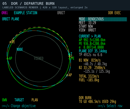
Scenario 5: departure, 30 seconds after engagement. DOR BURN; TO GO is about 487 m/s. The B1/B2 rows retain the planned burn budgets.
-
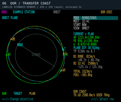
Scenario 6: the same transfer coasting. B1 is DONE. DOR COAST applies no translation thrust and prepares guidance for the next burn; TO GO now refers to that next correction.
-
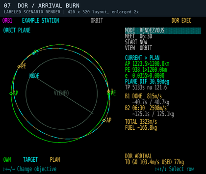
Scenario 7: arrival correction. DOR ARRIVAL has begun before the planned meeting time. Live TO GO differs from the original B2 estimate as guidance corrects the actual trajectory.


ALIGN uses rotational RCS before allowing a burn. It captures within 2 degrees with total angular rate below 0.5 degree/second for at least half a second; more than 5 degrees of attitude error or 2 degrees/second of angular rate returns it to ALIGN. Continuous entry and powered station transfers retain captured thrust through correcting rates up to 5 degrees/second; the initial capture and 5-degree attitude-error limit still apply. The commanded slew rate is limited to 5 degrees/second per body axis, with braking based on available torque. These are DOR alignment limits. Small velocity trims below 2 m/s within the same burn phase retain the established nose direction instead of chasing a reversing near-zero vector; bounded translation controls handle those trims.
The controller uses the vehicle's existing RCS force caps, inertia, lever arms, current mass, installed augmentation-system health, wing damage, electrical power and wear. Rotational effort consumes fuel through the existing propulsion model. DOR can use installed rotational RCS independently of the manual augmentation toggle and its IAS fade. It does not teleport attitude or grant extra torque. Main-engine spool-down and translation-RCS filtering still take time; holding commands off is not an instantaneous removal of residual thrust. The main engines do the bulk orbital acceleration. While aligned, transverse RCS supplies a proportional correction to the thrust direction; small terminal trims retain their separate translation authority. IDEAL duration/fuel and ALL USED measure different things: the former is a main-engine estimate, while the latter includes the fuel actually consumed by all thrusters and idle operation since engagement.
WAIT and COAST allow free attitude control. You may turn the ship in pitch, yaw and roll to look around while DOR remains engaged and the route stays armed. DOR does not force an immediate return to the next burn direction. With the controls released, gentle rotational RCS follows the changing local horizon, lowering the nose as a forward-facing ship travels around Vieneo. It preserves your chosen attitude relative to that changing horizon rather than forcing the nose onto the flight path or restoring level roll. The correction follows measured motion and Vieneo’s rotation.
When the executor requests a departure, correction or arrival burn, DOR switches to ALIGN, reacquires the burn direction and level roll, and waits for pointing/rate capture before allowing translation thrust. WAIT/COAST alone never command translation thrust. START NOW or reaching a scheduled burn time does not bypass ALIGN. Looking away may therefore add alignment time before the next burn, and the clearance check can refuse that delay. During active burns, remaining delta-V is recalculated from the actual state; it need not decrease smoothly or equal the original burn budget. Completion requires the controller to settle near its goal, so finite burns can finish later than the initial estimate.
DOR on the wide FMA
On the wide flight-mode annunciator (FMA2), DOR appears once in the upper engagement/source cell while DOR is on. It remains DOR during atmospheric ascent even when the ordinary AFCS performs the commanded heading and pitch control. The cell immediately below replaces A/T with the current DOR phase:
| Indication | Meaning |
|---|---|
| WAIT | Awaiting launch or a scheduled maneuver. Guidance that is temporarily unavailable, stale or frozen also shows WAIT; check the DOR page for the reason. |
| VTOL | DOR's initial vertical liftoff segment. |
| BURN | Translational thrust is commanded, including translation RCS where used. This is a command indication, not proof of achieved thrust or engine performance. |
| BRAKE | Powered entry or a powered prograde station transfer commands reverse braking; entry protection can also select braking to respect its limits. |
| RCS | Attitude-only RCS demand or recent rotational thruster activity, without a commanded translational burn. In a powered prograde station transfer, RCS also identifies the controlled translation-RCS segment with negligible fore/aft main demand; ALIGN remains visible. This can appear while the pilot adjusts attitude or the controller follows the changing horizon during coast. Brief pulses are grouped into a readable indication; negligible residual demand does not switch the phase label. |
| COAST | No translational burn or indicated attitude-RCS pulse. Read the attitude cells as well: an entry attitude hold can remain active without translation thrust. |
The lower lateral and vertical cells describe attitude control. HDG and PIT identify the AFCS heading/pitch climb; PIT and FPA show their selected angle in magenta beneath the active vertical cell, in degrees. ALIGN means DOR is acquiring or holding the commanded attitude, including after capture during a burn. It stays visible while that attitude remains under DOR control. An assigned NAV departure still follows the selected navigation course; its lateral DOR cell uses ALIGN to identify controlled attitude. The upper lateral and vertical row remains available for armed LOC and G/S.
In normal orbital WAIT or COAST, blank lower attitude cells mean DOR has released its commanded attitude: the pilot may turn the vehicle to look around without cancelling the route. RCS can still appear for those rotations or horizon-following assistance. Blank cells during Flight Freeze or unavailable guidance do not indicate a healthy free-coast state; inspect the DOR page. Manual attitude input during an armed ground launch wait cancels that wait. During ALIGN, a burn or powered ascent/entry, manual attitude input takes over and disconnects DOR.
The unused gray ALTm label and magenta 0.000 disappear together. A nonzero selected altitude remains visible. An active or armed altitude hold at zero is meaningful and remains displayed, including ALTa at zero AGL. After DOR disengages, the normal A/F or TVM source and any active A/T indication return. The orbital-burn MECO countdown remains on the DOR page; it is not an FMA phase.
DOR on the compact FMA
On the E-10 and A-4, DOR appears at the upper left of the PFD attitude indicator and A/T at the upper right while DOR controls thrust. The two-column FMA shows steady ALIGN in the active guidance cells while DOR acquires or holds attitude. During aircraft-controlled ascent it shows HDG and PIT or FPA when those guidance modes are active. The source label does not alternate with the axis commands.
Released axes are blank, allowing manual attitude changes while the route remains armed; ALIGN means attitude control remains active even when already aligned. Unavailable or stale guidance also blanks these cells: check the Orbit page for route and execution status. Armed LOC/G/S remain in the upper row. The compact PFD does not have FMA2's separate DOR phase cell; follow the Orbit page's phase and thrust information.
Rendezvous completion and TVM
After a successful RENDEZVOUS, DOR automatically hands control to TVM with TVM SET 0.000 km/s, keeping the same selected station or spacecraft. The page reports RENDEZVOUS COMPLETE / TVM and the normal Autoflyte disconnect sound plays once as DOR switches off. This happens when the final position and velocity correction settles, not simply when MEET reaches zero or B2 starts.
TVM commands a velocity match with the selected target; it does not hold the 5 km trail position or provide collision avoidance or automatic docking. Monitor separation and take control for the final docking approach. A manual DOR cancellation or an automatic abort does not engage TVM. ADJUST ORBIT and OVERFLY finish with their normal DOR disengagement.
Powered correction clearance
DOR rechecks each correction from the measured state using a finite powered forecast with Vieneo gravity and the same guidance retargeting law. It budgets alignment as unpowered coast, reserves engine spool and reverser response time, then credits bounded available thrust. Main-engine authority includes current mass, wear, engine health, power and the existing engine derating; small trims use the weaker translation limit. WAIT and COAST receive no hypothetical thrust credit.
The powered-correction check retains surface clearance for RENDEZVOUS and ADJUST ORBIT and the stricter 100 km / 10 Pa requirements for OVERFLY. OVERFLY still checks the remaining approach and continuing orbit and reduces optional position-closing commands that would spoil clearance.
The forecast is a bounded two-body estimate with constant mass and ideal steering after alignment. It is not a complete actuator, drag, lift, terrain or heating simulation. DOR rechecks when actual measurements change; unavailable authority, inadequate alignment time, or an unsafe powered response can still disconnect it. This vacuum correction forecast applies to the orbital leg. Powered launch/ascent and REENTRY use their separate controllers. FINAL ILS can continue through an aircraft-mode descent and arm the ordinary LOC/G/S capture; flare and touchdown remain manual.

If no qualifying correction exists, DOR clears its thrust and attitude commands, disconnects with the existing sound, and retains a reason such as DOR: NO CLEAR CORRECTION, DOR: CORRECTION MARGIN LOST, DOR: FINAL ORBIT UNSAFE or DOR: COAST CLEARANCE LOST. A delayed departure can report DOR: DEPARTURE COAST UNSAFE. Alignment checks the measured unpowered path for the estimated turning time and engine response, followed by the powered correction: DOR: ALIGN MARGIN LOST means it cannot safely spend that time turning. OVERFLY retains its atmospheric-clearance requirement; other orbital objectives retain their existing surface-clearance checks and atmospheric cautions. DOR: NO ATTITUDE CONTROL means the attitude data or required rotational authority is unavailable. Disconnecting does not recover an unsafe trajectory. Inspect your actual PE and warnings, then take over or select a different valid recovery plan.
Use DOR off to take over. Manual thrust-increase/decrease key commands also disengage it. Pitch/yaw/roll inputs in WAIT or COAST leave DOR engaged. During ALIGN or either active burn (BURN or ARRIVAL), a pitch, yaw or roll key command disconnects DOR immediately; joystick pitch, roll or yaw input outside the configured dead zone also disconnects it. Those disconnects use the existing Autoflyte disconnect sound. Stale guidance, invalid control data and Flight Freeze suppress rotational commands. Normal control resumes through the existing manual controls after disconnect. Changing planning values, losing/changing a rendezvous target, losing cockpit power, docking/landing, or changing/resetting the vehicle's flight state cancels execution. After a cancellation, inspect the reason and solve again before re-engaging. VIEW changes alone are safe to make during execution.
Every transition from DOR on to off plays the existing Autoflyte disconnect sound once. This includes normal plan completion, automatic aborts, manual takeover, switching to TVM, and a disconnect caused by loss of cockpit power. Completion and abort messages remain visible so you can inspect the reason. Remaining off does not repeat the sound, and restoring power does not replay it; engaging DOR again re-arms the next disconnect. This behavior follows DOR engagement, without an altitude or airspeed cutoff, and also applies in the simulator.
Pass over a ground point

- Select a surface waypoint, then choose OVERFLY.
- Set ALT above the spherical reference surface, in 100 km steps, and PASS time, in five-minute steps.
- Select EXIT COAST to continue on the transfer orbit after the crossing, or EXIT CIRCULARIZE to establish a circular orbit after passing the waypoint.
- Set START, inspect the ground track and orbit views, and review the burn estimates before using DOR.
On entering OVERFLY, the planner searches for an early viable PASS time using the selected ALT, EXIT and START settings. It checks the route and continuing orbit against the OVERFLY clearance requirements below, available fuel and the preview's burn-duration limits. Automatic PASS suggestions also exclude orbital reversals. It searches up to six hours ahead in 30-second intervals, refines the first viable interval to one second, and adds up to 30 seconds of headroom when that later candidate also passes the checks. This is a useful starting estimate, not a guaranteed global minimum or a guarantee of flight performance. Very narrow windows can be missed. It does not minimize fuel.
While searching, FINDING PASS TIME replaces the plan and DOR cannot engage it. NO VIABLE PASS IN 6H means no candidate met these criteria in the bounded search; it does not prove that no possible route exists. Change ALT, EXIT or START, or choose a manual PASS time to inspect other estimates. Weather at the selected point is not an input to the transfer solver.
The initial countdown stays fixed once selected. Until you edit PASS directly, changes to ALT, EXIT or START/IN request a new suggestion. After a direct PASS edit, your chosen deadline is retained, including an invalid or warning-producing one; the planner does not silently move it back into a valid window. Decrease or increase the displayed remaining time in five-minute steps (30 seconds to six hours). To request another automatic starting estimate, leave OVERFLY and select it again. VIEW changes do not restart the search. Automatic suggestions never change an executing DOR plan; manually changing planning values still cancels execution.
The illustrations show the layout and an example of a rejected overflight plan.
Why a low pass may have no clear transfer: Reaching 200 km above the point is not enough if the approach dips into the atmosphere or the continuing orbit returns there. EXIT COAST requires the full continuing orbit to remain bound and clear. EXIT CIRCULARIZE adds an arrival burn, but cannot make an earlier atmospheric dip acceptable. Changing PASS, ALT or EXIT may produce a valid route. Manual PASS retains your requested deadline and may display a blocked trajectory; it cannot override OVERFLY atmospheric clearance. Long-burn estimates can still be inspected manually.
Overfly meets a moving ground location at a chosen time; it does not hover above it. A circularization burn belongs after the crossing and can change where the spacecraft travels afterward. The pass altitude is not clearance above local terrain.
Overfly atmospheric clearance
OVERFLY checks the waiting coast, approach to the waypoint and continuing orbit. Each must stay at or above 100 km MSL and have a conservative dynamic-pressure bound of 10 Pa or less. EXIT CIRCULARIZE also checks the unbraked arrival path over an estimated response interval before crediting the final circular orbit. A clear later circle does not excuse an earlier low pass. The solver prefers a qualifying transfer over a cheaper atmospheric alternative.
The pressure estimate uses Vieneo's 3.063 kg/m³ surface density, 7.5 km scale height and a conservative bound on air-relative speed at the lowest point of the checked arc. At orbital speed, this can require clearance higher than 100 km. These are operational planning checks, not a validated heating envelope, drag-integrated trajectory or guarantee of finite-burn performance. These checks use Vieneo's atmosphere; the 100 km planning reference is not a physical atmospheric boundary.
Steady red PLAN MIN, COAST MIN or CORRECTION MIN identifies which trajectory falls below 100 km, with its minimum altitude in km MSL. EXEC PATH <100km identifies another low path checked by the executor. These can warn while your present altitude is much higher. The current-coast indication clears at 105 km to prevent flicker; its displayed number remains the actual predicted minimum during that hysteresis interval. This does not relax the solver's 100 km limit. Ground/reset state clears stale orbital warnings. Pressure advisories such as COAST ATM q>10Pa stay amber when there is no low-altitude warning. Warnings remain visible during both EXEC blink phases and after an abort.
A blocked preview shows NO PLAN, ATM PASS - NO PLAN and MIN … km / BLOCKED where a rejected trajectory is available. DOR cannot engage that preview. Atmospheric penetration remains possible to display for other orbital objectives, and the atmospheric stages of SURFACE PLAN remain planning-only; this OVERFLY restriction is not a blanket exclusion of atmospheric flight or reentry.
Cockpit Q is forward dynamic pressure in lb/ft²: Q = 2 is about 96 Pa, not 2 Pa. It is not a direct temperature or burn-up indication, and the planner's conservative arc-pressure bound is not the same as that instantaneous cockpit component.

Surface journey planning
For a ground or low-atmospheric departure, select point B on the normal target instrument. On this page choose MODE SURFACE PLAN, then ROUTE and TRIP while on the ground, or PASS when already airborne. For a departure from orbit or an orbital station, use the REENTRY controls below instead. Docking prevents execution, not planning. SURFACE PLAN remains planning-only after undocking; a qualifying REENTRY plan in the automated-entry controller can be executed.
Local trips: SURFACE PLAN shows NO PLAN / TOO SHORT when the departure and destination are less than 5 km apart, including their height difference. It does not generate a climb path, fuel estimate or initial time search for these trips. A coincident destination on the ground shows ALREADY AT B. Fly the local hop using ordinary flight controls or suitable Autoflyte modes; changing TRIP/PASS or forcing ATM, SUB or ORB does not create a local takeoff/hover/landing profile. This is a limit of the surface planner, not a vehicle flight limit. Orbital REENTRY and an entry already in progress are exempt.
| ROUTE | Proposed profile |
|---|---|
| AUTO | Compare the three route families at the selected TRIP duration or PASS deadline. Choose the lowest estimated fuel among candidates that pass the simplified model checks. AUTO may choose a different family when the selected time changes. |
| ATM | A powered atmospheric profile, climbing to 20 km MSL, traversing toward B, then descending. Only offered for departures at or below 40 km in this planning mode. It is not a simulation of wing-borne cruise. |
| SUB | Powered climb and boost, a ballistic coast with a surface-intersecting osculating orbit, then powered braking and descent. The coast ends before the intersection. |
| ORB | Powered climb and boost, a circular coast nominally at 400 km MSL, then powered braking and descent. This need not complete a revolution. |
TRIP is the requested travel duration before departure. While on the ground, TRIP 30:00 means a 30-minute journey starting when you depart. Waiting on the ground does not consume that allowance. At liftoff the deadline is fixed and the row becomes PASS, counting down to arrival. Landing restores duration planning. An already-airborne surface preview uses PASS from the time it is selected.
Adjust TRIP/PASS in five-minute steps using the value shown (30 seconds to six hours). This is a timing constraint, not an AUTO preference switch. The comparison shows each family's estimated fuel and MODEL FIT, THRUST LIMIT, FUEL LIMIT, IAS LIMIT or another reason. A forced ATM/SUB/ORB choice is retained even when invalid; AUTO does not silently replace it. If nothing fits, AUTO can display a rejected candidate for inspection. The upper-right header says INVALID in red; PLAN ONLY is reserved for a fitting preview, and NO PLAN means no candidate is available. The rejected path and estimates remain visible to help you adjust the timing; they are not achievable flight commands. Longer times are not guaranteed to help: gravity support consumes fuel and the search covers only a limited family of profiles.
On first selecting this objective, the module searches for an initial model-fitting trip time up to six hours: two-minute trial spacing, ten-second refinement of the first fitting bracket. FINDING TRIP TIME identifies the grounded search; NO FITTING TRIP IN 6H means this bounded search found none, not that every possible trajectory is impossible. Airborne previews use FINDING INITIAL PASS / NO FITTING PASS IN 6H. A manual edit keeps your chosen duration or deadline, including an invalid one. Changing ROUTE requests a new suggestion only before the time has been edited manually. Leaving and reselecting SURFACE PLAN restarts automatic initialization. The search never rewrites an executing orbital plan.
The amber path joins the measured initial state to B's position at PASS, accounting for Vieneo's rotation. PLANE 3D and TRACK can show the whole journey even before takeoff. For space profiles, markers 1–4 indicate the end of climb, start of coast, start of braking and start of descent/entry; B is the future destination. These are preview phase boundaries, not flight-director commands. ATM has only its final B marker. The top flight-phase label describes your current state, independently of the proposed route.
| Surface readout | Meaning |
|---|---|
| RANGE | Current great-circle distance to B, in km; not full path length. Below 10 km, one decimal place is shown (for example, 0.5 km). |
| TOP | Highest sampled profile altitude, km MSL above the spherical reference surface. |
| TOTAL | Integrated powered acceleration, expressed as delta-V in m/s, including gravity support and modeled body drag. This can greatly exceed the vehicle's speed; it is not a cruise-speed command. |
| FUEL | Estimated kg for the selected ideal profile, including idle flow during coasts. |
| THRUST | Peak fraction of available main-engine thrust. More than 100% is shown in red and invalidates the candidate. If IAS also exceeds its limit, the reason reads IAS / THRUST LIMIT so neither failure is hidden. |
| MAX q | Highest sampled dynamic pressure in kPa, based on mass density and air-relative speed. It is informational, not a validated heating or structural limit. |
MODEL FIT is not flight clearance. The preview uses Vieneo gravity and rotation, Vieneo's 3.063 kg/m³ surface density and 7.5 km density scale height, vehicle main thrust, altitude efficiency, fuel flow, wear and empirical body drag. Cruise at 20 km, the 100 km powered-segment interface and nominal 400 km orbital coast are planning choices, not atmospheric boundaries.
These ground-departure powered segments assume ideal thrust direction. They do not simulate RCS-axis limits, vehicle attitude changes, spool response, wing lift, wing/tail/wave drag, wind, clouds, weather avoidance, heating or terrain. ATM supports weight with thrust, so its fuel estimate is not a prediction of ordinary wing-borne Autoflyte cruise. Sampled geometry checks a reference sphere; it does not establish terrain clearance or that point B is a suitable landing site. Fuel comparisons and AUTO's choice are therefore comparisons within this simplified model, not a global optimum or a recommendation to fly the displayed path. Direction reversals remain visibly cautioned.
PLAN ONLY / ATM HANDOFF means the atmospheric stages require separate pilot/Autoflyte operation. SURFACE PLAN provides no automatic mode handoff, takeoff, atmospheric guidance, hover or landing. Orbital REENTRY has its own entry controller described below. The end-state is an ideal planning endpoint at B, not a landing command. Pressing DOR on a surface preview leaves execution off and plays the Autoflyte disconnect cavalry sound once to acknowledge the refusal. Holding the key does not repeat the sound. Existing executable ADJUST ORBIT, RENDEZVOUS and OVERFLY plans remain separate.
The surface-preview illustrations use PASS for the journey time; grounded controls display TRIP.
-
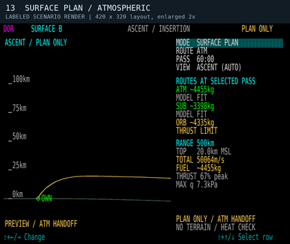
Scenario 13: ATM, 500 km in 60 minutes. Local ascent preview and route comparison. The large TOTAL includes ideal powered gravity support.
-
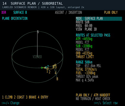
Scenario 14: SUB at the same PASS. Whole-route PLANE 3D view while still on the ground, with ballistic coast and numbered phase boundaries.
-
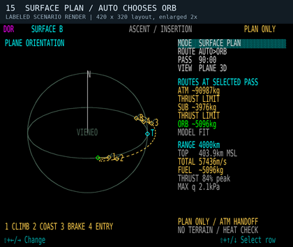
Scenario 15: AUTO, 4000 km in 90 minutes. ORB fits the simplified model while ATM and SUB exceed thrust. This demonstrates the PASS constraint, not certified flight performance.


Reentry and atmospheric entry
Select the intended surface waypoint on the usual navigation instrument. For an orbital departure, choose REENTRY. Planning is available while docked; undock before engaging DOR. The automated-entry controller can fly an ENTRY READY profile from at least 100 km MSL to its atmospheric handoff. It requires current air data, main/reverse and translation thrust, and a clean configuration: gear, flaps and spoilers retracted, bay closed and no significant icing. A plan lacking those inputs remains PLAN ONLY. Below 100 km, a new entry shows ENTRY START BELOW 100km and no powered profile is searched; handoff settings remain available. An entry already executing continues on its committed guidance through this altitude.
TARGET AUTO is selected when a new destination is initialized. DOR searches handoff altitude and TAS within its supported candidate range, checking stall margin, aerodynamic lift, braking, IAS, AFT and body-axis load limits before transferring to A/F. H ALT and H TAS show the selected result. The former 30 km / 0.5 km/s pair is only a possible manual target. Choose TARGET SET to retain explicit values, or edit H ALT/H TAS to switch to SET. Switching to SET copies the currently displayed solution. For FINAL ILS or VISUAL the handoff keeps descending toward final; FINAL HOLD requests level altitude/heading/TAS capture. HANDOFF is time to the aircraft-guidance transition, not touchdown. Automatic timing selects the earliest feasible handoff in the searched family; at the same deadline it prefers lower fuel. This is not a global time optimum or a guarantee of terrain clearance.
| Control | Meaning |
|---|---|
| ROUTE AUTO | Compare direct powered entry and coast-then-entry at the selected handoff time. Among model-fitting candidates, choose the lower estimated fuel requirement. This is a bounded search, not a global optimum. |
| ROUTE ORB | Remain on the measured current orbit for a selected coast, then enter. The preview does not first force the ship into a nominal 400 km orbit. |
| ROUTE SUB | Begin a direct powered entry after allowing time to align, without a discretionary orbital coast. Its feasibility depends on the requested time, position, velocity, weight and available thrust. |
| TARGET | AUTO searches a controllable A/F handoff; SET uses pilot-selected altitude and speed. |
| H ALT | Computed handoff altitude in AUTO, km MSL. Editing selects SET; adjust in 5 km steps, from 15 to 60 km. |
| H TAS | Computed air-relative handoff speed in AUTO, km/s. Editing selects SET; adjust in 0.1 km/s steps, from 0.1 to 1.5 km/s. This is not IAS or orbital speed. |
| HANDOFF | Requested remaining time, adjusted in five-minute steps. A shorter time may require greater powered acceleration or braking, or have no fitting candidate. |
ATM remains an atmospheric-departure option in SURFACE PLAN. It is not offered as an orbital entry shortcut. Ground/low-atmospheric SURFACE PLAN retains its separate AUTO / ATM / SUB / ORB route families and TRIP/PASS arrival at B; the new entry controls describe an atmospheric handoff before B.
D marks deorbit/start of the powered profile, E the sampled crossing of 100 km, and H the atmospheric handoff. The 100 km marker is an operating reference, not a hard atmosphere boundary. Gray is the planned coast on the current orbit; amber is the proposed entry, including any intermediate transfer coast. The graphic area remains the same size in every view.
PEAK REV and RCS show the largest predicted fractions of available reverse-main and translation-RCS thrust anywhere in the entry. These are peaks, not constant throttle commands, and their peaks need not occur together. DOR uses the thrust needed to follow the selected profile rather than commanding 100% throughout. Translation RCS supplies vertical and sideways force that the modeled wings and mains do not provide, including descent shaping and weight support as orbital support diminishes. This profile is not an aerodynamic-only or minimum-RCS entry. The entry model uses current loaded mass, fuel consumption, main-engine condition, separate forward/reverse and up/down/side limits, engine response, Vieneo gravity/rotation/density, and the vehicle's clean wing/tail/body and Mach-dependent aerodynamic performance. It estimates AFT from the entry heat-transfer estimate. MAX q is the modeled effective aerodynamic pressure in kPa, including Mach effects; it is distinct from ambient-density dynamic pressure. Cockpit Q is in lb/ft². LOAD is estimated non-gravitational acceleration in standard Earth g units.
ENTRY FUEL estimates main-engine, translation-RCS and idle fuel through H ALT / H TAS. Attitude-control RCS, subsequent descent, approach and landing are not budgeted. Subtracting ENTRY FUEL from the tanks gives an incomplete entry-end estimate, not predicted fuel on landing. Actual corrections and weather can change consumption.
The entry preview reports peak IAS as a percentage of Vne and peak predicted AFT. It requires at most 95% of Vne, 100°C predicted AFT and 95% of each available thrust axis, plus its engine-response and attitude-rate checks. These are guidance margins; continue observing the vehicle’s operating limits. AFT forecasting uses Vieneo's model and the current measured temperature/wind; it does not forecast changing weather, clouds or turbulence along the route. ALPHA / NO TERRAIN CHECK remains a limitation: neither the entry nor the ILS descent has a terrain or obstacle database, weather avoidance, flare or touchdown controller. Keep entry procedures, AFT, IAS/Vne and flight path in view.
Entry profile choice: The automatic initial suggestion searches for the earliest fitting HANDOFF in its candidate family, refining to ten seconds. The descent geometry also reserves a steep atmospheric segment and the final approach. Manual HANDOFF selections remain fixed. DOR compares continuous powered entry with a finite-burn / coast / capture profile at the selected HANDOFF time. The latter can use stronger forward or reverse-main thrust before a second coast, followed by powered braking to the handoff altitude, speed and flight-path angle. Shortening HANDOFF permits greater thrust and fuel use where needed, while retaining the selected H ALT and H TAS and the same IAS/AFT, engine-response, attitude-rate and per-axis force checks. DOR chooses the lower estimated fuel among fitting candidates it finds at that time. Extra fuel cannot make every deadline feasible; the search does not certify the globally fastest entry. Longer journeys do not always use less fuel because orbital geometry and support against gravity also matter.
CONTINUOUS ENTRY identifies the original profile family. COAST mm:ss / mm:ss gives the countdowns to the start and end of the intermediate transfer coast. During that coast it changes to COAST END mm:ss, then COAST COMPLETE. The intermediate coast stays above the 100 km operating reference and permits small tracking corrections; this is not a physical atmosphere boundary. The amber proposed entry path includes this intermediate coast as well as its powered legs.
Entry thrust and interruptions: POWERED ENTRY follows the accepted profile. Main thrust can remain below 100%, or approach available authority when needed. The planner retains its 95% nominal per-axis reserve for feedback; a burn-and-coast profile is not an instruction to hold full throttle throughout. ENTRY TRANSFER COAST means translation is idle within the tracking corridor; ENTRY COAST / TRIM means corrections are being applied. DOR pre-aligns during the last 120 seconds before the next powered segment. Check the FMA: ALIGN means DOR is controlling attitude; when ALIGN is absent during free coast, the pilot may look around. IAS/AFT protection remains active and can end a coast early. The achieved handoff can be later than the requested time while the actual altitude, TAS, descent rate and position settle.
During an already executing reentry, ENTRY DATA WAIT means current air data is temporarily unavailable. DOR retains the accepted entry plan and suspends entry steering and thrust commands until fresh measurements return. It then reacquires attitude and continues from the measured flight state, including below 100 km MSL. While DOR remains engaged, temporary thrust inhibition leaves the reversers in their commanded direction while engine power decays. This continuation does not bypass the altitude requirement for starting a new entry. Manual disengagement cancels the mission and does not automatically resume it. If the data-wait indication persists, take control.
Entry readiness and configuration: A route can fit the fuel, thrust and temperature limits while the ship is not ready to execute it. PLAN ONLY with an amber CONFIG LANDING GEAR, CONFIG FLAPS, CONFIG SPOILERS, CONFIG AIRFRAME ICE or CONFIG CARGO BAY identifies the configuration that must be corrected. Air, thermal or performance data problems have their own messages. Retract gear, flaps and spoilers fully, close the bay and clear icing before entry. Landing gear must also have confirmed status: a GEAR DISAGREE condition or unknown gear status prevents entry even if the gear appears retracted. The DOR page continues to show CONFIG LANDING GEAR. READY / ENTRY READY and ARM DOR TO EXECUTE indicate that the entry readiness checks pass; selecting AUTO does not engage DOR.
If gear prevents engagement, DOR remains off, announces its disconnect sound and queues "Config. Landing gear." The refusal is also shown in red. Extending gear or losing confirmed gear status during an executing entry invalidates the clean profile and disconnects DOR, releasing its attitude and thrust commands with the same specific alert. Take control after a disconnect; DOR does not retract gear or automatically re-engage. A new entry still requires an origin at or above 100 km MSL. The queued gear phrase is discarded if the gear is confirmed fully retracted, power is lost, or the relevant vehicle/plan changes before playback. Normal gear use after the achieved atmospheric handoff does not trigger this entry-specific warning; the ordinary aircraft-mode limits still apply.
Entry load and skip protection
Entry planning uses one aerospace-class load envelope, common to aerospace vehicles: 5 G sideways, 10 G fore/aft, and a healthy-airframe normal-load range of −2.8 to +4.8 G. These are body-axis loads in standard G (9.80665 m/s²), not multiples of Vieneo surface gravity. The normal allowance is 3.8 G about the model's 1 G baseline; the separate occupant normal allowance is 5 G about that baseline. DOR reserves 5% of the usable allowances. There are no individual vehicle load ratings: mass, thrust, aerodynamic and thermal performance determine the trajectory within the common envelope.
Damage reduces the common airframe allowance according to the remaining strength of the weaker wing. The LOAD readout is the largest fraction of the usable body-axis limits, with a 95% planning ceiling; it is not a single universal G value. Damage can make a formerly feasible entry unavailable. Live control also budgets thrust against measured cockpit loads, including rotational effects.
The direct-entry profile must keep descending after entering through its 100 km planning interface. A predicted unplanned climb triggers SKIP LIMIT / RECOVER; excessive predicted or measured loads trigger LOAD LIMIT / RECOVER. DOR remains engaged, applies bounded recovery commands and may miss the selected handoff time. Recovery annunciations require two seconds of clear conditions before releasing. The 100 km interface is a mission-phase definition, not the edge of Vieneo's atmosphere. Intentional skip-entry profiles are not supported.
SKIP CHECKED / ENTRY identifies the planned check. LOAD RESERVE, SKIP / OVERSHOOT, A/F HANDOFF ENVELOPE or NO A/F HANDOFF FIT explain rejected candidates. Change the requested time or target settings, or address configuration/damage; the planner does not waive the limits for an earlier arrival. A/F handoff also requires usable aerodynamic lift and stall margin without relying on entry's vertical RCS. Crosswind crab is accounted for when checking runway alignment.
These checks account for Vieneo's atmosphere and the selected vehicle. They do not provide terrain or weather avoidance, guarantee control after catastrophic damage, or automate landing. The nominal 20° descent belongs to the later atmospheric approach; it is not an instruction to force a 20° flight path at orbital-entry speed.
Automated entry
- Start with a clean ship in orbit and select the surface destination. Use AUTO, H ALT 30 km and H TAS 0.5 km/s as initial handoff settings.
- Adjust HANDOFF until the preview says ENTRY READY. Shortening it asks for a faster journey; IAS RESERVE, AFT RESERVE, THRUST RESERVE, ATTITUDE RATE or SPOOL LIMIT identifies why a candidate is rejected. A longer time is not guaranteed to fit every geometry. Check fuel and the whole proposed path.
- Undock if necessary, then engage DOR. AUTO selects a route; it does not engage DOR by itself.
- During the initial coast DOR pre-aligns for entry. A burn-and-coast profile can include another coast before final braking; monitor its coast countdowns and ALIGN indication. During POWERED ENTRY it keeps the nose into the air-relative direction of travel with a small positive angle of attack, using forward or reverse mains and bounded translation RCS. Braking does not require pointing the tail into the airflow. Manual attitude input during ALIGN or powered entry disconnects DOR.
- ENTRY LIMIT / BRAKING means the short-term forecast predicts excessive IAS or AFT. DOR gives braking and descent control priority over the requested time; HANDOFF may be missed. This is active protection, not a guarantee against every disturbance or an instruction to ignore warnings.
- At the achieved entry handoff, expect the ordinary DOR disconnect sound once. FINAL HOLD transfers to ALT/HDG/TAS hold. VISUAL and FINAL ILS continue in FPA/NAV/TAS through the aircraft-mode descent described below when current air data and flight conditions are suitable. It retains the incoming descent angle at handoff. If automatic continuation is unavailable, its message identifies the refusal and the pilot must manage the selected guidance and speed. HANDOFF PASSED alone is not completion: altitude, airspeed, descent rate, position and attitude must also converge.
- To resume normal flight, cancel the entry TAS hold with the DOR control or by moving a physical throttle lever. The lateral and vertical guidance modes remain until changed or disconnected. Disconnecting the aircraft autopilot also ends the TAS hold. After entry handoff, TAS hold continues with HDG, NAV or LOC and PIT, VS, ALTm, ALTa, FPA or G/S. Selecting SpeedPitch, Roll, an off mode or TVM ends it. Ordinary gear/flap/spoiler changes after handoff retain TAS hold with updated drag compensation; icing, an open bay, unavailable/stale air data or lost authority still cancel it. Change H TAS on the DOR page to adjust the held speed. Outside automatic runway descent, manage speed for ATC routing, descent and approach: a fixed TAS can produce increasing IAS as you descend. During automatic runway descent, changing the target or a flight-guidance mode/target cancels the continuation, except that ILS LOC/G/S arming and LOC capture preserve managed vertical descent; the pilot’s selected mode remains in force. Cancelling TAS hold also stops automatic descent updates, so check the FMA and take over the remaining flight path.
Arrival planning and final approach
Choose FINAL on REENTRY with Shift + arrow controls before engaging DOR. A newly selected surface target resets FINAL to HOLD. These controls do not add automated landing to ground-departure SURFACE PLAN.
| FINAL | Behavior |
|---|---|
| HOLD | Entry followed by ALT/HDG/TAS hold. Remaining descent is manual. |
| ILS | Select a powered, serviceable runway ILS or its unambiguously associated inbound LOM. After entry, NAV/FPA and A/T manage the steep descent and transition to the final approach. LOC/G/S are armed near the final join when capture conditions are suitable. |
| VISUAL | Select a runway threshold with an inbound heading. The second FINAL row selects 10–30 km in 2 km steps, initially 10 km. NAV/FPA and A/T manage descent to the 3° final join, then retain NAV/FPA/TAS for pilot-managed final approach and landing. |
| VTOL (PLAN) | Preview a hover gate 100 m above the surface point. Loaded vertical-thrust authority must support the vehicle. Entry retains its altitude/heading/speed handoff; the preview does not switch to TVM, descend, hover or land automatically. |
Steep descent: For ILS or VISUAL, the entry aims to cross H ALT at H TAS while descending on the runway's extended centerline. The initial settings are 30 km MSL / 0.5 km/s TAS. The following descent targets −20° FPA and blends gradually into the final −3° path. It does not level off at 30 km. NAV can converge from a lateral offset; a fixed 1 km corridor is not required at the atmospheric handoff. The DOR page identifies DESC 20>3deg and STEEP DESCENT / NAV FPA SPD. The FMA shows the aircraft guidance modes and A/T after DOR hands over.
Final geometry: At least 10 km is reserved for 3° final. ILS uses a unique loaded inbound outer marker when it is farther out; a nearer marker does not shorten that minimum. Otherwise the initial final distance is 10 km. The ILS join is 15 m below the nominal beam, within its descending-capture tolerance. The receiver uses MSL height difference and slant DME. VISUAL uses a 3° ray above the runway tangent, corrected for Vieneo's curvature. The displayed final altitude includes runway elevation and is MSL, not terrain clearance.
For VMCI RWY 36, WOOKE is about 21.35 km out. With runway elevation about 5.954 km MSL, the beam is about 7.075 km MSL and the descending join about 7.060 km MSL. Approach on the published inbound side, course 360°. Use current navigation data if airport geometry changes.
Speed and thrust: The managed descent retains higher speed until denser air, predicted AFT or the braking distance to final calls for slowing. Its final IAS objective is the greater of Vref and 1.3 times current stall speed. The forecast uses Vieneo's atmosphere and Mach-dependent drag, with a 90% Vne planning target and 95°C thermal target below the entry's 95% Vne/100°C limits. These are guidance margins; continue observing the vehicle’s operating limits. Pitch can shallow to preserve speed margin. Engine response and reverse-bucket travel are allowed for before final speed capture.
Thrust may be idle, forward or reverse. Strong burns are used where the selected entry needs them; it is not a continuous full-throttle command. Idle is possible when the path and energy permit it, but holding speed against atmospheric drag can require forward thrust. Gear, flaps and spoilers remain pilot-operated and their live drag/stall effects affect A/T. A fixed TAS is not a safe substitute for monitoring IAS during descent.
ILS capture: Near the final join, a suitably aligned and stabilized descending aircraft retains NAV/FPA with LOC and G/S armed; the page reads ILS READY / LOC GS ARMED. If a LOM was selected, the navigation reference switches to its runway threshold. The ordinary receiver controls LOC/G/S capture. Shift+C and Shift+V remain the manual arm controls. Manual LOC arming and capture preserve managed vertical descent; a different selected vertical mode or changed target takes precedence. Completed automatic arming is not repeatedly reissued after pilot disarming.
VISUAL final: At the join the page reads VISUAL FINAL / NAV FPA SPD. The automatic descent schedule ends, leaving a selected −3° FPA, NAV and TAS hold. Manage the remaining final, configuration, speed, flare and touchdown. This is not an autoland.
Limits and takeover: HANDOFF and ENTRY FUEL still describe orbital entry to H ALT/H TAS; they exclude the additional descent and landing. The search checks a bounded set of entry candidates, not a certified global minimum journey time. Neither entry nor managed descent has terrain or obstacle look-ahead or a changing-weather forecast. Radio height can stop a descent toward nearby terrain but cannot establish route clearance. Lost data, changed approach, excessive IAS/AFT, inadequate stall margin or a missed join ends managed descent; when its control ownership and data permit, it captures current MSL altitude for takeover. Freeze pauses the controller. A cancelled continuation does not restart automatically. The pilot remains responsible for ATC routing, terrain/weather avoidance and landing.
The gray final line is reference geometry, not a terrain-checked forecast of the whole atmospheric descent. SELECT RUNWAY / LIVE ILS or SELECT RUNWAY THRESHOLD identifies missing or unusable runway data. Changed associated approach data during entry stops DOR with APPROACH DATA CHANGED.
Flight path angle (FPA)
The normal vertical flight-director cycle is PIT → FPA → VS → SPD → ALTm → ALTa → PIT. FPA follows Pitch directly when available. At ground contact, below 0.010 km/s horizontal groundspeed, or with invalid path data, the vertical-mode key skips FPA and continues to VS, SPD and the available altitude modes. ALTa is skipped when the required ground-height data are unavailable; G/S remains separately armed. FPA captures the current ground-relative climb/descent angle. Use the existing vertical-target increase/decrease controls to adjust it; the selected signed angle appears in the flight-mode display. The selectable range is −20° to +20°. For a descending 3° path, select −3°.
FPA is the angle of travel relative to the local ground tangent, not nose pitch or angle of attack. The controller adjusts pitch as the measured path changes; its pitch command changes by at most 3°/s. Aircraft response, wind, lift and available thrust still determine whether it can achieve the selected path. FPA controls neither lateral course nor speed, and does not provide terrain avoidance, a flare or touchdown. It can be used as a flight-director cue or with the normal aircraft autopilot; it is not an orbital insertion solver or a DOR ascent profile.
At ground contact, below 0.010 km/s horizontal groundspeed, or with invalid path data, FPA returns to PIT at the current pitch. It does not automatically re-arm: select FPA again after establishing forward flight. This prevents a hover or nearly vertical trajectory from being treated as an ordinary forward flight path. Ground-relative geometry remains defined at high speed, but selecting FPA does not establish atmospheric control authority in suborbital coast or orbit.
The CSV records selected FPA/course, AFCS ground/vertical speeds, arrival choice, final-gate geometry and its advisory status. The companion plan file labels the ILS beam ils_glidepath_reference and the other advisory final lines final_advisory_not_executed. ILS continuation recording also includes its active/armed state, gate altitude and distance, inbound distance and target IAS. Actual lateral/vertical thruster output remains recorded; a human's recorded firings are not replayed as the optimal control sequence.
| Message | Meaning / next action |
|---|---|
| VACUUM ESTIMATE | An orbital estimate is available. It assumes two-body coasting between instantaneous planned burns. |
| LONG BURN - ESTIMATE / FINITE BURN NOT CORRECTED | The preview's instantaneous-burn approximation is weak for the estimated duration. Live DOR corrects from actual state, but the original time, path and fuel are estimates. |
| PLAN ATM PASS / COAST ATM q>10Pa / CORRECTION ATM q>10Pa / CURRENT ATM q>10Pa / ATMOSPHERIC PASS / ATMOSPHERIC TARGET | Pressure advisory above 10 Pa, or a target explicitly in atmospheric-flight reference mode. The actual predicted coast is refreshed during execution. Other orbital modes can retain atmospheric estimates; OVERFLY must satisfy its stricter clearance requirements. |
| PLAN MIN / COAST MIN / CORRECTION MIN / EXEC PATH <100km | Steady red low-altitude warning identifying the affected trajectory. The numerical minima are km MSL. COAST MIN assumes no further burns and can differ from PLAN MIN ALT. The current-coast warning clears at 105 km; this is annunciation hysteresis only. |
| ATM PASS - NO PLAN / MIN … km / BLOCKED | An inspectable OVERFLY candidate fails atmospheric clearance. Change PASS, ALT or EXIT; DOR cannot execute it. |
| DOR: TIMING INTERRUPTED | A guidance update was delayed during ascent or an orbital maneuver. DOR disconnects; check the current flight state before re-engaging. An executing reentry instead retains its plan and waits for fresh air data when needed. |
| ENTRY DATA WAIT | An executing reentry is waiting for current air data with entry steering and thrust commands suspended. The accepted entry remains engaged and resumes from measured state when valid data returns. Manual disengagement still cancels it. |
| DOR: NO CLEAR CORRECTION / CORRECTION MARGIN LOST / FINAL ORBIT UNSAFE / COAST CLEARANCE LOST / DEPARTURE COAST UNSAFE | Execution stopped because the updated trajectory or correction fails its checks. Thrust commands are cleared and the disconnect sounds once. The existing trajectory still needs pilot attention. |
| SURFACE INTERSECTION / NO CLEAR TRANSFER | The requested shape intersects Vieneo, or no acceptable transfer was found. Raise the requested periapsis or change the timing/objective. |
| INSUFFICIENT FUEL / PERFORMANCE UNAVAILABLE | Fuel or propulsion data do not support execution. A geometric estimate alone is not an executable DOR plan. |
| BURN TIME PASSED / ARRIVAL TIME PASSED | The selected deadline has passed. Edit the time to request a new one; these are real countdowns, not indefinitely rolling delays. |
| SELECT NAV TARGET / NO TARGET TRAJECTORY | Select a usable target, or choose ADJUST ORBIT. |
| DOR: UNDOCK TO EXECUTE | An orbital plan can be previewed while attached to a station, but DOR cannot arm or execute it until undocked. Undocking does not engage DOR automatically. SURFACE PLAN remains planning-only. A qualifying automated-entry REENTRY still requires undocking before execution. |
| NO DEPARTURE STATE / POWER OFF | The departure reference is unavailable or unsupported, or cockpit power is off. A valid station attachment permits previews; an unsupported containment frame does not. |
| ASCENT PROFILE REQUIRED | The selected vacuum orbital objective has no powered launch solution. Choose MODE RENDEZVOUS for a continuous launch to an orbital target, or MODE PARKING ORBIT for a standalone parking-orbit climb. |
| VTOL READY / ASCENT READY | The ascent controller is ready with the current inputs. Ground LAUNCH AUTO can arm while its comparison is running, but requires a completed, current, fuel-fitting solution before committing departure; ground RENDEZVOUS requires one for LAUNCH NOW too. This is not a full-flight fuel, time or terrain-clearance guarantee. See scheduled launch and airborne pickup. |
| VTOL LIFT / ATTITUDE LIMIT / ASCENT DATA INVALID | Check loaded vertical-thrust authority, level ground attitude, configuration and valid current air data. |
| ASCENT LIMIT / IDLE | The short-term ascent forecast is at its IAS or AFT guard. Positive main thrust is reduced; monitor the actual path. |
| INSERTION COMPLETE / REPLAN | Standalone PARKING ORBIT has ended at the parking orbit. Select and review RENDEZVOUS separately to continue. A mission begun in ground RENDEZVOUS instead transfers automatically. |
| DOR: NO TRANSFER AT INSERTION / TRANSFER FUEL SHORTFALL / MEET BURN TIME LIMIT | The achieved insertion state cannot support the transfer at the original MEET with the remaining fuel/time. DOR stops; review the condition and a new plan before re-engaging. |
| DOR: MEET MISSED DURING ASCENT / MEET MISSED AT INSERTION / ASCENT TARGET INVALID / INSERTION TARGET INVALID | The mission has insufficient remaining MEET time or no usable orbital target. DOR stops rather than changing the deadline or treating parking insertion as rendezvous completion. |
| PLAN ONLY / ATM HANDOFF | The displayed candidate is preview-only; DOR cannot execute it. Ground-departure SURFACE PLAN remains preview-only. REENTRY needs a qualifying ENTRY READY profile in the automated-entry controller. |
| INVALID / MODEL FIT / THRUST LIMIT / FUEL LIMIT / IAS LIMIT / IAS / THRUST LIMIT | Result of the surface preview’s simplified checks. MODEL FIT does not certify terrain, heating, weather, maneuverability or landing. |
| NO TERRAIN / HEAT CHECK | The preview does not check terrain or heating. Automated-entry REENTRY predicts heat but its ALPHA / NO TERRAIN CHECK indication still means there is no terrain protection. |
| ENTRY READY / IAS RESERVE / AFT RESERVE / THRUST RESERVE / ATTITUDE RATE / SPOOL LIMIT | Automated-entry preview result. READY passes the modeled checks; other messages identify a rejection. None certifies terrain clearance or landing. |
| ENTRY DATA / CONFIG | Entry cannot execute with the current air data, configuration or departure altitude. Check clean configuration, valid measurements and an orbital departure. |
| ENTRY TRANSFER COAST / ENTRY COAST / TRIM | Intermediate coast of a burn-and-coast entry. Translation is idle within the tracking corridor or applies bounded corrections. ALIGN indicates attitude control for the next burn; IAS/AFT protection remains active. |
| ENTRY LIMIT / BRAKING | Active entry protection prioritizes braking and arresting descent over the requested handoff time. Monitor the actual trajectory. |
| MODEL FIT / HEAT UNCHECKED | The preview fits the planning model without a heat check; it is not executable automated entry. |
| HANDOFF BELOW TARGET | Raise H ALT above the destination elevation. |
| ENTRY DATA UNAVAILABLE / ENTRY GEOMETRY / NO COAST / ENTRY FIT | Required performance data or a fitting entry candidate is unavailable. Inspect the selected time, route and handoff settings. |
| ENTRY FIRST / NO ROUTE AT THIS PASS | Direct ATM is outside its departure-height range, or no candidate was available at this deadline. Change ROUTE/PASS or use separate entry procedures. |